✨ Elevate Your Projects with OLED Brilliance!
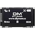
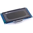
The diymore I2C Display Module is a 2.42-inch OLED screen featuring a 128x64 pixel resolution, driven by the SSD1309 chip. It supports both SPI and IIC interfaces, making it a versatile choice for Arduino projects and DIY electronics. Perfect for developers looking to enhance their displays with high-quality graphics.


| Graphics Card Interface | Integrated |
| System Bus Standard Supported | SATA 3 |
| USB 2.0 | 4 |
| Total Usb Ports | 4 |
| Platform | Not Machine Specific |
| Memory Storage Capacity | 64 GB |
| Main Power Connector Type | DC power jack |
| Processor Socket | DIP |
| Compatible Devices | Personal Computer, Tablet, Mobile Phone, Development Board |
| Chipset Type | SSD1309 |
H**S
Works great!
I used the Adafruit_SSD1306 library with a Moteino M0 board and it worked with no issues. It is setup to work with SPI by default, which is a little confusing because the board is labeled for I2C. Luckily several of the reviews pointed out that discrepancy so it was no big deal.I used hardware SPI and wired SDA->MOSI, SCL->SCK, GND->Ground, VCC->3v, and the remaining 3 pins to whatever digital output pins you want. I also modified the Adafruit example sketch to use hardware SPI (the sketch defaults to software SPI). So the initialization line I used is as follows:Adafruit_SSD1306 display(OLED_DC, OLED_RESET, OLED_CS);The display is nice and bright and daylight readable. I plan to buy many more of these in the future. Great display.
J**S
Very nice OLED, got it working via SPI and I2C despite incorrect documentation
Working on some projects with a Raspberry Pi Pico using a ported SSD1306 library. My project required I2C communication and I had some difficulty at first. I validated the OLED worked via SPI, so after a bit of fiddling I figured out the combination:1. Move R4 resistor to R32. Bridge the R5 pads (0 ohm resistor, solder bridge or wire will work)3. Connect the RES pin to source voltage (connected to RUN pin on Pi Pico)4. Connect the GND, VCC, SDA, SCL lines normallyStep 3 wasn't documented anywhere I could find. Figured it out after some Googling and trial and error. After all was said and done, I was able to run this OLED at 3.3v and 5v via SPI and I2C. I tested I2C up to 800 kHz (didn't try higher) and it worked great. I don't know if running it out of spec will kill it faster, but I was impressed with the variety of options that worked.The display refreshes just a tad slower than the smaller OLED displays I have, but that's not a knock against it. I have the green and blue versions and both look amazing and perform great for my use case. As someone else said, the pins are labeled in a weird way, but it's easy enough to figure out what goes where. Would definitely get more if needed.
Q**Y
Works well on I2C
You need to move a resistor and jumper as per product description. Also RST needs to be set, either by pull up or pull down. You can connect RST to ENA pin on your devkit, if it's available, or use something like this:pinMode( 5, OUTPUT); // RES Pin DisplaydigitalWrite( 5, LOW);delay (100);digitalWrite( 5, HIGH);Also, it works with the Adafruit SSD1306 library, no need to hunt for a 1309 library.
�**�
It's cool until it's warm.
This was going to be a review about how to use this device with a teensy 4.0, but I guess now it's a review about how this device tried to catch fire while I was eating a sandwich. And also how to use it with a teensy 4.0. I had this device working and displaying a demo, and suddenly and spontaneously made sparking sounds and released acrid smoke. If you intend to use this device, I'd advise housing it in refractory and making it easily replaceable.First, connect SCL as labelled on the OLED to SCK on the teensy, SDA on the OLED to MOSI on the teensy, and the other 3 signal pins wherever. Next, open arduino library manager and install adafruit SSD1306, and instandiate a display object using the native SPI interface. I couldn't get the software one (the one that takes pin numbers for data and clock rather than &SPI) to work.Adafruit_SSD1306 display(128, 64, &SPI, OLED_DC, OLED_RESET, OLED_CS);After this, the display API worked, the bytes in the buffer returned by display.getBuffer are arranged in 8 pixel tall columns starting at the upper left.Also, why is the labeling for I2C while the default mode is SPI? Also, can I get a replacement that isn't melted?
O**R
Good display but not super easy to use as I2C as it should be
Have to move a resistor that is tiny, tiny like the size of a grain of rice. And find the right I2C then it works fine otherwise, it won't work as I2C. Also no instructions and no drivers given so using Adafruit driver. All in all works fine but you have to work around these issues. If you cannot solder tiny, tiny parts then skip this one if you want I2C.
J**8
Works fine with 3 different SPI Libraries
Libraries tried so far: Adafruit SSD1306; SSD1306Ascii; U8g2. All of them have an option for software SPI which is what I used with the Raspberry Pico board. I'm pretty sure if it will work with this board it would work with any. I haven't tried I2C mode yet, but I don't really feel the need too considering how easy the SPI was to utilize, especially since you could even bit bang the SPI. It's basically an upscaled 1306 and therefore has the same resolution so, in theory, the same libraries should work. I got the yellow version on sale and am not disappointed. I have had multiple problems trying to get my dual rp2040 project up and running, but luckily this has not been one.
S**A
Solid option for a monochrome OLED display
Easy to use and set up. There are Arduino libraries available to work with this. The display is nice and high contrast.
Z**R
Works great and looks even better!
Love the extra screen real estate. I'm building a cyberdeck/smart watch project with this screen and it is a fantastic fit for the purchase. Highly recommend Green.
Trustpilot
4 days ago
1 month ago